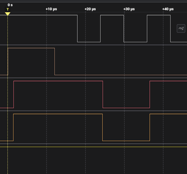
//CH32V003
// -----------------------
//1 - PD4 PD3 - 20
//2 - PD5(UTX) PD2 - 19
//3 - PD6(URX) (SWIO)PD1 - 18
//4 - PD7 (MISO)PC7 - 17
//5 - PA1 (MOSI)PC6 - 16
//6 - PA2 (SCK) PC5 - 15
//7 - VSS (GNG) PC4 - 14
//8 - PD0 PC3 - 13
//9 - VDD PC2 - 12
//10- PC0 PC1 - 11
// -----------------------
#include "debug.h"
#include "string.h"
/* SPI Mode Definition */
#define HOST_MODE 0
#define SLAVE_MODE 1
/* SPI Communication Mode Selection */
//#define SPI_MODE HOST_MODE
#define SPI_MODE HOST_MODE
/* Global define */
#define Size 32
/* Global Variable */
uint8_t rxBuf[34];
uint16_t rxvalue1;
uint16_t rxvalue2;
uint8_t readBits(uint16_t value, uint8_t bit_position) {
return (value >> bit_position) & 1; // Returns 1 if the specified bit is 1, otherwise returns 0.
}
void Delay_Ns(uint32_t ns) {
for(int i=0;i<ns;i++) {
asm("NOP"); // Insert an empty command and wait
}
}
void GPIO_INIT(void)
{
GPIO_InitTypeDef GPIO_InitStructure={0};
RCC_APB2PeriphClockCmd(RCC_APB2Periph_GPIOC,ENABLE);
GPIO_InitStructure.GPIO_Pin = GPIO_Pin_2 | GPIO_Pin_3 |GPIO_Pin_0;
GPIO_InitStructure.GPIO_Mode = GPIO_Mode_Out_PP;
GPIO_InitStructure.GPIO_Speed=GPIO_Speed_50MHz;
GPIO_Init(GPIOC, &GPIO_InitStructure);
}
void EXTI0_INT_INIT(void)
{
GPIO_InitTypeDef GPIO_InitStructure = {0};
EXTI_InitTypeDef EXTI_InitStructure = {0};
NVIC_InitTypeDef NVIC_InitStructure = {0};
/* GPIO PC1 setting */
RCC_APB2PeriphClockCmd(RCC_APB2Periph_AFIO | RCC_APB2Periph_GPIOC, ENABLE);
GPIO_InitStructure.GPIO_Pin = GPIO_Pin_1;
GPIO_InitStructure.GPIO_Mode = GPIO_Mode_IPU;
GPIO_Init(GPIOD, &GPIO_InitStructure);
/*EXTernal Interrupt(EXTI)
/* GPIOD ----> EXTI_Line1 */
GPIO_EXTILineConfig(GPIO_PortSourceGPIOC, GPIO_PinSource1);
EXTI_InitStructure.EXTI_Line = EXTI_Line1;
EXTI_InitStructure.EXTI_Mode = EXTI_Mode_Interrupt;
EXTI_InitStructure.EXTI_Trigger = EXTI_Trigger_Rising;//EXTI_Trigger_Falling EXTI_Trigger_Rising
EXTI_InitStructure.EXTI_LineCmd = ENABLE;
EXTI_Init(&EXTI_InitStructure);
/* NVIC*/
NVIC_InitStructure.NVIC_IRQChannel = EXTI7_0_IRQn;
NVIC_InitStructure.NVIC_IRQChannelPreemptionPriority = 1;
NVIC_InitStructure.NVIC_IRQChannelSubPriority = 2;
NVIC_InitStructure.NVIC_IRQChannelCmd = ENABLE;
NVIC_Init(&NVIC_InitStructure);
}
void EXTI7_0_IRQHandler(void) __attribute__((interrupt("WCH-Interrupt-fast")));
void EXTI7_0_IRQHandler(void)
{
EXTI_ClearFlag(EXTI_Line1); // rest exti
for(int i=0; i<16; i++){
// uint16_t test=0b0101010101010000;
//GPIO_WriteBit(GPIOC, GPIO_Pin_2, readBits(rxvalue1, 15-i));
//GPIO_WriteBit(GPIOC, GPIO_Pin_3, readBits(rxvalue2, 15-i));
GPIOC->BSHR = (readBits(rxvalue1, 15-i)<<2|readBits(rxvalue2, 15-i)<<3|~readBits(rxvalue1, 15-i)<<2+16|~readBits(rxvalue2, 15-i)<<3+16);
if (i==0){
Delay_Us(18);
Delay_Ns(3);
}else{
Delay_Us(8);
Delay_Ns(1);
}
}
// GPIO_WriteBit(GPIOC, GPIO_Pin_0, readBits(rxvalue1, 14));
GPIOC->BSHR = (1<<2+16|1<<3+16);
// GPIO_WriteBit(GPIOC, GPIO_Pin_2, 0);
// GPIO_WriteBit(GPIOC, GPIO_Pin_3, 0);
}
/*********************************************************************
* @fn SPI_FullDuplex_Init
*
* @brief Configuring the SPI for full-duplex communication.
*
* @return none
*/
void SPI_FullDuplex_Init(void)
{
GPIO_InitTypeDef GPIO_InitStructure={0};
SPI_InitTypeDef SPI_InitStructure={0};
RCC_APB2PeriphClockCmd( RCC_APB2Periph_GPIOC | RCC_APB2Periph_SPI1, ENABLE );
GPIO_InitStructure.GPIO_Pin = GPIO_Pin_4;
GPIO_InitStructure.GPIO_Mode = GPIO_Mode_Out_PP;
GPIO_InitStructure.GPIO_Speed = GPIO_Speed_50MHz;
GPIO_Init( GPIOC, &GPIO_InitStructure );
#if (SPI_MODE == HOST_MODE)
GPIO_InitStructure.GPIO_Pin = GPIO_Pin_5;
GPIO_InitStructure.GPIO_Mode = GPIO_Mode_AF_PP;
GPIO_InitStructure.GPIO_Speed = GPIO_Speed_30MHz;
GPIO_Init( GPIOC, &GPIO_InitStructure );
GPIO_InitStructure.GPIO_Pin = GPIO_Pin_7;
GPIO_InitStructure.GPIO_Mode = GPIO_Mode_IN_FLOATING;
GPIO_Init( GPIOC, &GPIO_InitStructure );
GPIO_InitStructure.GPIO_Pin = GPIO_Pin_6;
GPIO_InitStructure.GPIO_Mode = GPIO_Mode_AF_PP;
GPIO_InitStructure.GPIO_Speed = GPIO_Speed_30MHz;
GPIO_Init( GPIOC, &GPIO_InitStructure );
#elif (SPI_MODE == SLAVE_MODE)
GPIO_InitStructure.GPIO_Pin = GPIO_Pin_5;
GPIO_InitStructure.GPIO_Mode = GPIO_Mode_IN_FLOATING;
GPIO_Init( GPIOC, &GPIO_InitStructure );
GPIO_InitStructure.GPIO_Pin = GPIO_Pin_7;
GPIO_InitStructure.GPIO_Mode = GPIO_Mode_AF_PP;
GPIO_InitStructure.GPIO_Speed = GPIO_Speed_30MHz;
GPIO_Init( GPIOC, &GPIO_InitStructure );
GPIO_InitStructure.GPIO_Pin = GPIO_Pin_6;
GPIO_InitStructure.GPIO_Mode = GPIO_Mode_IN_FLOATING;
GPIO_Init( GPIOC, &GPIO_InitStructure );
#endif
SPI_InitStructure.SPI_Direction = SPI_Direction_2Lines_FullDuplex;//(SPI_DIRECTION_2LINES_RXONLY //SPI_Direction_2Lines_FullDuplex
#if (SPI_MODE == HOST_MODE)
SPI_InitStructure.SPI_Mode = SPI_Mode_Master;
#elif (SPI_MODE == SLAVE_MODE)
SPI_InitStructure.SPI_Mode = SPI_Mode_Slave;
#endif
SPI_InitStructure.SPI_DataSize = SPI_DataSize_8b;
SPI_InitStructure.SPI_CPOL = SPI_CPOL_High;// SPI_CPOL_Low SPI_CPOL_High
SPI_InitStructure.SPI_CPHA = SPI_CPHA_2Edge;
SPI_InitStructure.SPI_NSS = SPI_NSS_Soft;
SPI_InitStructure.SPI_BaudRatePrescaler = SPI_BaudRatePrescaler_8;
SPI_InitStructure.SPI_FirstBit = SPI_FirstBit_MSB;//SPI_FirstBit_MSB
SPI_InitStructure.SPI_CRCPolynomial = 7;
SPI_Init( SPI1, &SPI_InitStructure );
SPI_Cmd( SPI1, ENABLE );
}
void SPISendReceiveBytes(uint8_t *sendData, uint8_t *getData, uint32_t length)
{
for(int i = 0; i < length; i ++)
{
//Send SPI Byte
while( SPI_I2S_GetFlagStatus( SPI1, SPI_I2S_FLAG_TXE ) == RESET ); // wait while flag is zero or TX buffer not empty
SPI_I2S_SendData( SPI1, sendData[i] );
//Receive SPI Byte
while(SPI_I2S_GetFlagStatus( SPI1, SPI_I2S_FLAG_RXNE ) == RESET ); // wait while flag is zero or RX buffer is empty
getData[i] = SPI_I2S_ReceiveData( SPI1 );
}
}
void printBinary(int num) {
for (int i = 15; i >= 0; i--) {
printf("%d", (num >> i) & 1);
}
}
/*********************************************************************
* @fn main
*
* @brief Main program.
*
* @return none
*/
int main(void)
{
SystemCoreClockUpdate();
Delay_Init();
USART_Printf_Init(115200);//460800
printf("SystemClk:%d\r\n",SystemCoreClock);
printf( "ChipID:%08x\r\n", DBGMCU_GetCHIPID() );
GPIO_WriteBit(GPIOC, GPIO_Pin_4, Bit_RESET);
GPIO_ResetBits(GPIOC, GPIO_Pin_4); // CS LOW
GPIO_ResetBits(GPIOC, GPIO_Pin_2); // LOW
GPIO_ResetBits(GPIOC, GPIO_Pin_3); // LOW
#if (SPI_MODE == SLAVE_MODE)
printf("Slave Mode\r\n");
Delay_Ms(1000);
#endif
SPI_FullDuplex_Init();
#if (SPI_MODE == HOST_MODE)
printf("Host Mode\r\n");
Delay_Ms(2000);
#endif
GPIO_INIT();
EXTI0_INT_INIT();
uint8_t txBuf[34];
for(int i = 0; i < 34; i++){
txBuf[i] = 0x0;
rxBuf[i] = 0x0;
}
txBuf[0] = 0x03;
while(1)
{
GPIO_SetBits(GPIOC, GPIO_Pin_4); // CS HIGH
Delay_Us(5);
GPIO_ResetBits(GPIOC, GPIO_Pin_4); // CS LOW
SPISendReceiveBytes(txBuf,rxBuf,6);
GPIO_SetBits(GPIOC, GPIO_Pin_4); // CS HIGH
Delay_Us(5);
GPIO_ResetBits(GPIOC, GPIO_Pin_4); // CS LOW
rxvalue1=(rxBuf[2] << 8) | rxBuf[3];
rxvalue2=(rxBuf[4] << 8) | rxBuf[5];
printBinary(rxvalue1);
printf(" ");
printBinary(rxvalue2);
printf("\r\n");
//}
Delay_Ms(10);
}
}


コメント
コメントを投稿