RTOS: OLED SSD1306 I2C in English
 int_fast16_t res; //for checking adc converting
(if you want to use library, visits here...)
Trying to get the OLED SSD1306 to work with TI-RTOS.
With DriverLib, I was able to use it by simply downloading a library that a volunteer had made, but I couldn't find it unless I made a library for TI-RTOS.
However, I had to create a library for the TI-RTOS to use it. Creating one from scratch is a lot of work, so I used the libraries of my predecessors.
Download the necessary files from
https://github.com/boykod/SSD1306-I2C-library-for-MSP430-432
now we need 2 files at least.
font6x8.h
address.h

Both should be placed in the same hierarchy as the thread's c-file.
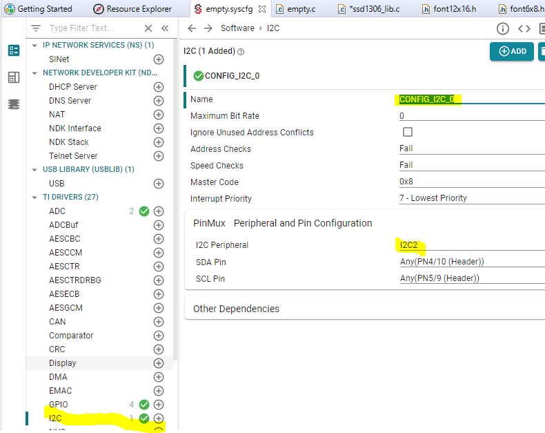
Open the Syscfg file and add I2C, give it a name and select which pin you want to use as I2C. I2C2 is selected here. PN4 is SDA and PN5 is SCL.
It's a bit long, but I'll copy and place mainThread5 and the necessary functions below.
(I'll make it into a library later, but the purpose is to see how it works.)
****************from here ***************
void *mainThread5(void *arg0)
{
I2C_init();
I2C_Params_init(&iP);
iP.bitRate = I2C_400kHz;
iP.transferMode = I2C_MODE_BLOCKING;
i2c = I2C_open(CONFIG_I2C_0, &iP);
// Wait 10ms
Task_sleep(10000 / Clock_tickPeriod);
// Initialize SSD1306
ssd1306Init(i2c);
fillDisplay (i2c,0x00);
while (1) {
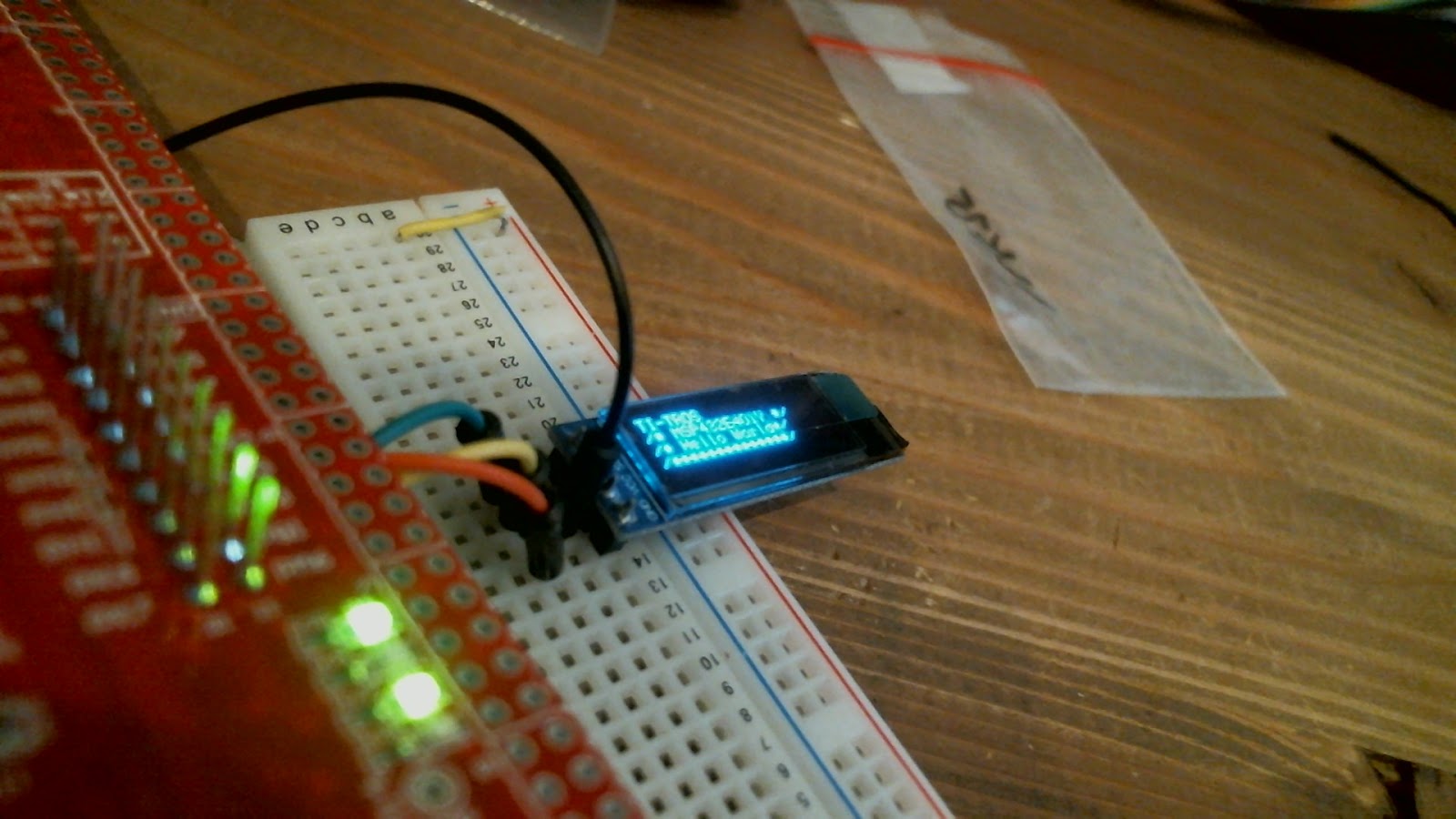
draw6x8Str(i2c,0, 0, "TI-TROS", 1,0);
draw6x8Str(i2c,0, 1, "/* MSP432E401Y */",1,0);
draw6x8Str(i2c,0, 2, "/* Hello World*/",1,0);
draw6x8Str(i2c,0, 3,"/**************/",1,0);
Task_sleep(250000 / Clock_tickPeriod);
}
}
void ssd1306Init(I2C_Handle i2c) {
ssd1306_command(i2c, SSD1306_DISPLAY_OFF); /*0xAE:■Entire Display OFF */
ssd1306_command(i2c, SSD1306_SET_DISPLAY_CLOCK_DIV); /*0xD5:Set Display Clock Divide Ratio and Oscillator Frequency */
ssd1306_command(i2c, 0xF0); /*0xF0 original 0x80:Default Setting for Display Clock Divide Ratio and Oscillator Frequency that is recommended */
ssd1306_command(i2c, SSD1306_SET_MULTIPLEX_RATIO); /*0xA8: Set Multiplex Ratio */
#if (SSD1306_HEIGHT == 32)
ssd1306_command(i2c, 0x1F); /* 64 COM lines */
#elif
ssd1306_command(i2c, 0x3F);
#endif
ssd1306_command(i2c, SSD1306_SET_DISPLAY_OFFSET); /* 0xD3:Set display offset */
ssd1306_command(i2c, 0x00); /* 0 offset */
ssd1306_command(i2c, SSD1306_SET_START_LINE | 0x00); /* Set first line as the start line of the display */
ssd1306_command(i2c, SSD1306_SET_CHARGE_PUMP); /* Charge pump */
ssd1306_command(i2c, 0x14); /* Enable charge dump during display on */
ssd1306_command(i2c, SSD1306_MEMORY_ADDRESS_MODE); /*■Set memory addressing mode */
ssd1306_command(i2c, SSD1306_SET_LCOL_START_ADDRESS); /*■Horizontal addressing mode */
ssd1306_command(i2c, SSD1306_SEGMENT_REMAP | 0x01); /* Set segment remap with column address 127 mapped to segment 0 */
ssd1306_command(i2c, SSD1306_COM_SCAN_INVERSE); /* Set com output scan direction, scan from com63 to com 0 */
ssd1306_command(i2c, SSD1306_SET_COM_PINS_CONFIG); /* Set com pins hardware configuration */
#if (SSD1306_HEIGHT == 32)
ssd1306_command(i2c, 0x02); /* Alternative com pin configuration, disable com left/right remap */ //0x12
#elif
ssd1306_command(i2c, 0x12);
#endif
ssd1306_command(i2c, SSD1306_SET_CONTRAST); /* Set contrast control */
ssd1306_command(i2c, 0x80); /* Set Contrast to 128 */
ssd1306_command(i2c, SSD1306_SET_PRECHARGE_PERIOD); /* Set pre-charge period */
ssd1306_command(i2c, 0xF1); /* Phase 1 period of 15 DCLK, Phase 2 period of 1 DCLK */
ssd1306_command(i2c, SSD1306_SET_VCOM_DESELECT_LVL); /* Set Vcomh deselect level */
ssd1306_command(i2c, 0x40); /* Vcomh deselect level */
ssd1306_command(i2c, SSD1306_ENTIRE_DISPLAY_RESUME); /* Entire display ON, resume to RAM content display */
ssd1306_command(i2c, SSD1306_NORMAL_DISPLAY); /* Set Display in Normal Mode, 1 = ON, 0 = OFF */
ssd1306_command(i2c, SSD1306_DISPLAY_ON); /* Display on in normal mode */
}
void ssd1306_command(I2C_Handle i2c, UInt8 cmd)
{
UInt8 buf[2];
buf[0] = 0;
buf[1] = cmd;
sendData(i2c, &buf[0], 2);
}
void sendData(I2C_Handle i2c, Void * data, size_t count) // Needs to include a 0x40 at the very beginning
{
I2C_Transaction txn;
txn.writeBuf = (void *)data;
txn.writeCount = count;
txn.readCount = 0;
txn.readBuf = NULL;
txn.slaveAddress = SSD1306_ADDRESS;
I2C_transfer(i2c, &txn);
}
void setCursor (I2C_Handle i2c,unsigned char x, unsigned char p) {
ssd1306_command(i2c,SSD1306_SET_LCOL_START_ADDRESS | (x & 0x0F));
ssd1306_command(i2c,SSD1306_SET_HCOL_START_ADDRESS | (x >> 4));
ssd1306_command(i2c,SSD1306_SET_PAGE_START_ADDRESS | p);
}
void fillDisplay(I2C_Handle i2c,unsigned char param) {
unsigned char page, x;
unsigned char *dataBuffer;
dataBuffer = malloc(129);
dataBuffer[0] = SSD1306_DATA_MODE;
for (page = 0; page < 8; page++) {
setCursor(i2c,0, page);
for (x = 0; x < 128; x++) {
dataBuffer[x + 1] = param;
}
sendData(i2c, &dataBuffer[0], 129);
//sendData(dataBuffer, 129);
}
free(dataBuffer);
}
void draw6x8Str(I2C_Handle i2c,unsigned char x, unsigned char p, const char str[],
unsigned char invert, unsigned char underline) {
unsigned char i, j, b, buf[FONT6X8_WIDTH + 1];
unsigned int c;
i = 0;
buf[0] = SSD1306_DATA_MODE; // fist item "send data mode"
while (str[i] != '\0') {
if (str[i] > 191)
c = (str[i] - 64) * FONT6X8_WIDTH;
else
c = str[i] * FONT6X8_WIDTH;
if (x > (SSD1306_WIDTH - FONT6X8_WIDTH - 1))
{
x = 0;
p++;
};
if (p > 7) p = 0;
setCursor(i2c,x, p);
for (j = 0; j < FONT6X8_WIDTH; j++)
{
if (underline)
b = font6x8[(unsigned int)(c + j)] | 0x80;
else
b = font6x8[(unsigned int)(c + j)];
if (invert)
buf[j + 1] = b;
else
buf[j + 1] = ~b;
};
sendData(i2c, &buf[0], FONT6X8_WIDTH + 1);
//sendData(buf, FONT6X8_WIDTH + 1); // send the buf to display
x += FONT6X8_WIDTH;
i++;
};
}
**********************************************
Then, continue editing in the same file. Include the two downloaded headers.
/*SSD1306*/
#include "address.h"
#include "font6x8.h"
Also, since I2C is used, take out the comment out in front of #include <ti/drivers/I2C.h>, or
Place #include <ti/drivers/I2C.h>.
/* Driver Header files */
#include <ti/drivers/GPIO.h>
#include <ti/drivers/I2C.h>
I2C_Params iP;
I2C_Handle i2c;
The handle is commonly used in functions, so define it in a global location.
Finally, modify cfg file to add thread5 as follows.

PN4 is SDA and PN5 is SCL.
Connect GND and VCC of OLED to GND and 3.3V respectively, SDA to SDA, and SCL to SCL.
If there are no errors in the build, flush it and you will see
The OLED will display the specified character.
*****************************************
/*
* Copyright (c) 2015-2019, Texas Instruments Incorporated
* All rights reserved.
*
* Redistribution and use in source and binary forms, with or without
* modification, are permitted provided that the following conditions
* are met:
*
* * Redistributions of source code must retain the above copyright
* notice, this list of conditions and the following disclaimer.
*
* * Redistributions in binary form must reproduce the above copyright
* notice, this list of conditions and the following disclaimer in the
* documentation and/or other materials provided with the distribution.
*
* * Neither the name of Texas Instruments Incorporated nor the names of
* its contributors may be used to endorse or promote products derived
* from this software without specific prior written permission.
*
* THIS SOFTWARE IS PROVIDED BY THE COPYRIGHT HOLDERS AND CONTRIBUTORS "AS IS"
* AND ANY EXPRESS OR IMPLIED WARRANTIES, INCLUDING, BUT NOT LIMITED TO,
* THE IMPLIED WARRANTIES OF MERCHANTABILITY AND FITNESS FOR A PARTICULAR
* PURPOSE ARE DISCLAIMED. IN NO EVENT SHALL THE COPYRIGHT OWNER OR
* CONTRIBUTORS BE LIABLE FOR ANY DIRECT, INDIRECT, INCIDENTAL, SPECIAL,
* EXEMPLARY, OR CONSEQUENTIAL DAMAGES (INCLUDING, BUT NOT LIMITED TO,
* PROCUREMENT OF SUBSTITUTE GOODS OR SERVICES; LOSS OF USE, DATA, OR PROFITS;
* OR BUSINESS INTERRUPTION) HOWEVER CAUSED AND ON ANY THEORY OF LIABILITY,
* WHETHER IN CONTRACT, STRICT LIABILITY, OR TORT (INCLUDING NEGLIGENCE OR
* OTHERWISE) ARISING IN ANY WAY OUT OF THE USE OF THIS SOFTWARE,
* EVEN IF ADVISED OF THE POSSIBILITY OF SUCH DAMAGE.
*/
/*
* ======== empty.c ========
*/
#include <unistd.h> /* For usleep() */
#include <stdint.h>
#include <stddef.h>
#include <string.h>/* to use memset and strcmp*/
#include <stdio.h> /* to use sprintf */
#include <stdlib.h>/* to use sprintf */
/*SSD1306*/
#include "address.h"
#include "font6x8.h"
/* Driver Header files */
#include <ti/drivers/GPIO.h>
#include <ti/drivers/I2C.h>
I2C_Params iP;
I2C_Handle i2c;
// #include <ti/drivers/SPI.h>
#include <ti/drivers/UART.h>
extern UART_Handle uart;
extern UART_Params uartParams;
#include <ti/drivers/ADC.h>
// #include <ti/drivers/Watchdog.h>
/* Driver configuration */
#include "ti_drivers_config.h"
#include <ti/sysbios/knl/Task.h> //to use task sleep Task.h is needed.
#include <ti/sysbios/knl/Clock.h> //of caurase, clock.h also.
#include <ti/sysbios/BIOS.h>
/* declaration of original functions*/
void gpioButtonFxn0(uint_least8_t index);
float getADC14(int channel);
void ssd1306Init();
void ssd1306_command(I2C_Handle i2c, UInt8 cmd);
void sendData(I2C_Handle i2c, Void * data, size_t count);
void fillDisplay(I2C_Handle i2c,unsigned char param);
void draw6x8Str(I2C_Handle i2c,unsigned char x, unsigned char p, const char str[],
unsigned char invert, unsigned char underline);
void setCursor (I2C_Handle i2c,unsigned char x, unsigned char p) ;
/* ADC conversion result variables */
float adcValue0Volt[2];
/*
* ======== mainThread ========
*/
void *mainThread0(uint16_t arg0, UArg arg1)
{
/* 1 second delay */
// uint32_t time = 1000;
/* Call driver init functions */
GPIO_init();
/* Configure the LED pin */
GPIO_setConfig(CONFIG_GPIO_LED_0, GPIO_CFG_OUT_STD | GPIO_CFG_OUT_LOW);
/* Turn on user LED */
GPIO_write(CONFIG_GPIO_LED_0, CONFIG_GPIO_LED_ON);
while (1) {
GPIO_toggle(CONFIG_GPIO_LED_0);
Task_sleep(((uint16_t)arg0) * (1000 / Clock_tickPeriod));
}
}
void *mainThread1(UArg arg0, UArg arg1)
{
/* 1 second delay */
// uint32_t time = 100; //msec
/* Call driver init functions */
GPIO_init();
/* Configure the LED pin */
GPIO_setConfig(CONFIG_GPIO_LED_1, GPIO_CFG_OUT_STD | GPIO_CFG_OUT_LOW);
/* Turn on user LED */
GPIO_write(CONFIG_GPIO_LED_1, CONFIG_GPIO_LED_ON);
while (1) {
GPIO_toggle(CONFIG_GPIO_LED_1);
Task_sleep(((UInt)arg0) * (1000 / Clock_tickPeriod));
}
}
void *mainThread2(UArg arg0, UArg arg1)
{
GPIO_init();
/* Configure the LED pin */
GPIO_setConfig(CONFIG_GPIO_LED_2, GPIO_CFG_OUT_STD | GPIO_CFG_OUT_LOW);
/* Turn on user LED */
GPIO_write(CONFIG_GPIO_LED_2, CONFIG_GPIO_LED_ON);
// GPIO_setCallback(CONFIG_GPIO_BTN_0, gpioButtonFxn0);
GPIO_enableInt(CONFIG_GPIO_BTN_0);
return 0;
}
void gpioButtonFxn0(uint_least8_t index)
{
// Toggle the LED
GPIO_toggle(CONFIG_GPIO_LED_2);
}
void *mainThread3(void *arg0)
{
const char echoPrompt[] = "Thread3:";
char UART_TX_buffer[32];
while (1) {
UART_write(uart, echoPrompt, sizeof(echoPrompt));
memset(UART_TX_buffer, 0x00, sizeof(UART_TX_buffer));
sprintf(UART_TX_buffer,"V=%f\n",adcValue0Volt[1]);
UART_write(uart, UART_TX_buffer, sizeof(UART_TX_buffer));
Task_sleep(500 * (1000 / Clock_tickPeriod));
}//end while
}
void *mainThread4(void *arg0)
{
const char echoPrompt[] = "Thread4:\n";
while (1) {
UART_write(uart, echoPrompt, sizeof(echoPrompt));
adcValue0Volt[1]=getADC14(1);
Task_sleep(500 * (1000 / Clock_tickPeriod));
}
}
float getADC14(int channel)
{
/* ADC conversion result variables */
uint16_t adcValue;
float adcValueVolt;
ADC_init();
ADC_Handle adc; //adc handle
ADC_Params params; //adc parameters
ADC_Params_init(¶ms); //initialization of parameters
switch(channel){
case 0:
adc = ADC_open(CONFIG_ADC_0, ¶ms); //open adc
break;
case 1:
adc = ADC_open(CONFIG_ADC_1, ¶ms); //open adc
break;
default:
adc = ADC_open(CONFIG_ADC_0, ¶ms); //open adc
}
int_fast16_t res; //for checking adc converting
res=ADC_convert(adc, &adcValue); //second argument should set address.
if (res == ADC_STATUS_SUCCESS) {
adcValueVolt = (float)ADC_convertRawToMicroVolts(adc, adcValue)/1000000.0;
}
ADC_close(adc);
return adcValueVolt;
}
void *mainThread5(void *arg0)
{
I2C_init();
I2C_Params_init(&iP);
iP.bitRate = I2C_400kHz;
iP.transferMode = I2C_MODE_BLOCKING;
i2c = I2C_open(CONFIG_I2C_0, &iP);
// Wait 10ms
Task_sleep(10000 / Clock_tickPeriod);
// Initialize SSD1306
ssd1306Init(i2c);
fillDisplay (i2c,0x00);
char OLED_buffer[32];
while (1) {
draw6x8Str(i2c,0, 0, "TI-RTOS", 1,0);
draw6x8Str(i2c,0, 1, "/* MSP432E401Y */",1,0);
draw6x8Str(i2c,0, 2, "/* Hello World*/",1,0);
memset(OLED_buffer, 0x00, sizeof(OLED_buffer));
sprintf(OLED_buffer,"V=%f",adcValue0Volt[1]);
draw6x8Str(i2c,0, 3,OLED_buffer,1,0);
Task_sleep(250000 / Clock_tickPeriod);
}
}
void ssd1306Init(I2C_Handle i2c) {
ssd1306_command(i2c, SSD1306_DISPLAY_OFF); /*0xAE:■Entire Display OFF */
ssd1306_command(i2c, SSD1306_SET_DISPLAY_CLOCK_DIV); /*0xD5:Set Display Clock Divide Ratio and Oscillator Frequency */
ssd1306_command(i2c, 0xF0); /*0xF0 original 0x80:Default Setting for Display Clock Divide Ratio and Oscillator Frequency that is recommended */
ssd1306_command(i2c, SSD1306_SET_MULTIPLEX_RATIO); /*0xA8: Set Multiplex Ratio */
#if (SSD1306_HEIGHT == 32)
ssd1306_command(i2c, 0x1F); /* 64 COM lines */
#elif
ssd1306_command(i2c, 0x3F);
#endif
ssd1306_command(i2c, SSD1306_SET_DISPLAY_OFFSET); /* 0xD3:Set display offset */
ssd1306_command(i2c, 0x00); /* 0 offset */
ssd1306_command(i2c, SSD1306_SET_START_LINE | 0x00); /* Set first line as the start line of the display */
ssd1306_command(i2c, SSD1306_SET_CHARGE_PUMP); /* Charge pump */
ssd1306_command(i2c, 0x14); /* Enable charge dump during display on */
ssd1306_command(i2c, SSD1306_MEMORY_ADDRESS_MODE); /*■Set memory addressing mode */
ssd1306_command(i2c, SSD1306_SET_LCOL_START_ADDRESS); /*■Horizontal addressing mode */
ssd1306_command(i2c, SSD1306_SEGMENT_REMAP | 0x01); /* Set segment remap with column address 127 mapped to segment 0 */
ssd1306_command(i2c, SSD1306_COM_SCAN_INVERSE); /* Set com output scan direction, scan from com63 to com 0 */
ssd1306_command(i2c, SSD1306_SET_COM_PINS_CONFIG); /* Set com pins hardware configuration */
#if (SSD1306_HEIGHT == 32)
ssd1306_command(i2c, 0x02); /* Alternative com pin configuration, disable com left/right remap */ //0x12
#elif
ssd1306_command(i2c, 0x12);
#endif
ssd1306_command(i2c, SSD1306_SET_CONTRAST); /* Set contrast control */
ssd1306_command(i2c, 0x80); /* Set Contrast to 128 */
ssd1306_command(i2c, SSD1306_SET_PRECHARGE_PERIOD); /* Set pre-charge period */
ssd1306_command(i2c, 0xF1); /* Phase 1 period of 15 DCLK, Phase 2 period of 1 DCLK */
ssd1306_command(i2c, SSD1306_SET_VCOM_DESELECT_LVL); /* Set Vcomh deselect level */
ssd1306_command(i2c, 0x40); /* Vcomh deselect level */
ssd1306_command(i2c, SSD1306_ENTIRE_DISPLAY_RESUME); /* Entire display ON, resume to RAM content display */
ssd1306_command(i2c, SSD1306_NORMAL_DISPLAY); /* Set Display in Normal Mode, 1 = ON, 0 = OFF */
ssd1306_command(i2c, SSD1306_DISPLAY_ON); /* Display on in normal mode */
}
void ssd1306_command(I2C_Handle i2c, UInt8 cmd)
{
UInt8 buf[2];
buf[0] = 0;
buf[1] = cmd;
sendData(i2c, &buf[0], 2);
}
void sendData(I2C_Handle i2c, Void * data, size_t count) // Needs to include a 0x40 at the very beginning
{
I2C_Transaction txn;
txn.writeBuf = (void *)data;
txn.writeCount = count;
txn.readCount = 0;
txn.readBuf = NULL;
txn.slaveAddress = SSD1306_ADDRESS;
I2C_transfer(i2c, &txn);
}
void setCursor (I2C_Handle i2c,unsigned char x, unsigned char p) {
ssd1306_command(i2c,SSD1306_SET_LCOL_START_ADDRESS | (x & 0x0F));
ssd1306_command(i2c,SSD1306_SET_HCOL_START_ADDRESS | (x >> 4));
ssd1306_command(i2c,SSD1306_SET_PAGE_START_ADDRESS | p);
}
void fillDisplay(I2C_Handle i2c,unsigned char param) {
unsigned char page, x;
unsigned char *dataBuffer;
dataBuffer = malloc(129);
dataBuffer[0] = SSD1306_DATA_MODE;
for (page = 0; page < 8; page++) {
setCursor(i2c,0, page);
for (x = 0; x < 128; x++) {
dataBuffer[x + 1] = param;
}
sendData(i2c, &dataBuffer[0], 129);
//sendData(dataBuffer, 129);
}
free(dataBuffer);
}
void draw6x8Str(I2C_Handle i2c,unsigned char x, unsigned char p, const char str[],
unsigned char invert, unsigned char underline) {
unsigned char i, j, b, buf[FONT6X8_WIDTH + 1];
unsigned int c;
i = 0;
buf[0] = SSD1306_DATA_MODE; // fist item "send data mode"
while (str[i] != '\0') {
if (str[i] > 191)
c = (str[i] - 64) * FONT6X8_WIDTH;
else
c = str[i] * FONT6X8_WIDTH;
if (x > (SSD1306_WIDTH - FONT6X8_WIDTH - 1))
{
x = 0;
p++;
};
if (p > 7) p = 0;
setCursor(i2c,x, p);
for (j = 0; j < FONT6X8_WIDTH; j++)
{
if (underline)
b = font6x8[(unsigned int)(c + j)] | 0x80;
else
b = font6x8[(unsigned int)(c + j)];
if (invert)
buf[j + 1] = b;
else
buf[j + 1] = ~b;
};
sendData(i2c, &buf[0], FONT6X8_WIDTH + 1);
//sendData(buf, FONT6X8_WIDTH + 1); // send the buf to display
x += FONT6X8_WIDTH;
i++;
};
}


コメント
コメントを投稿